
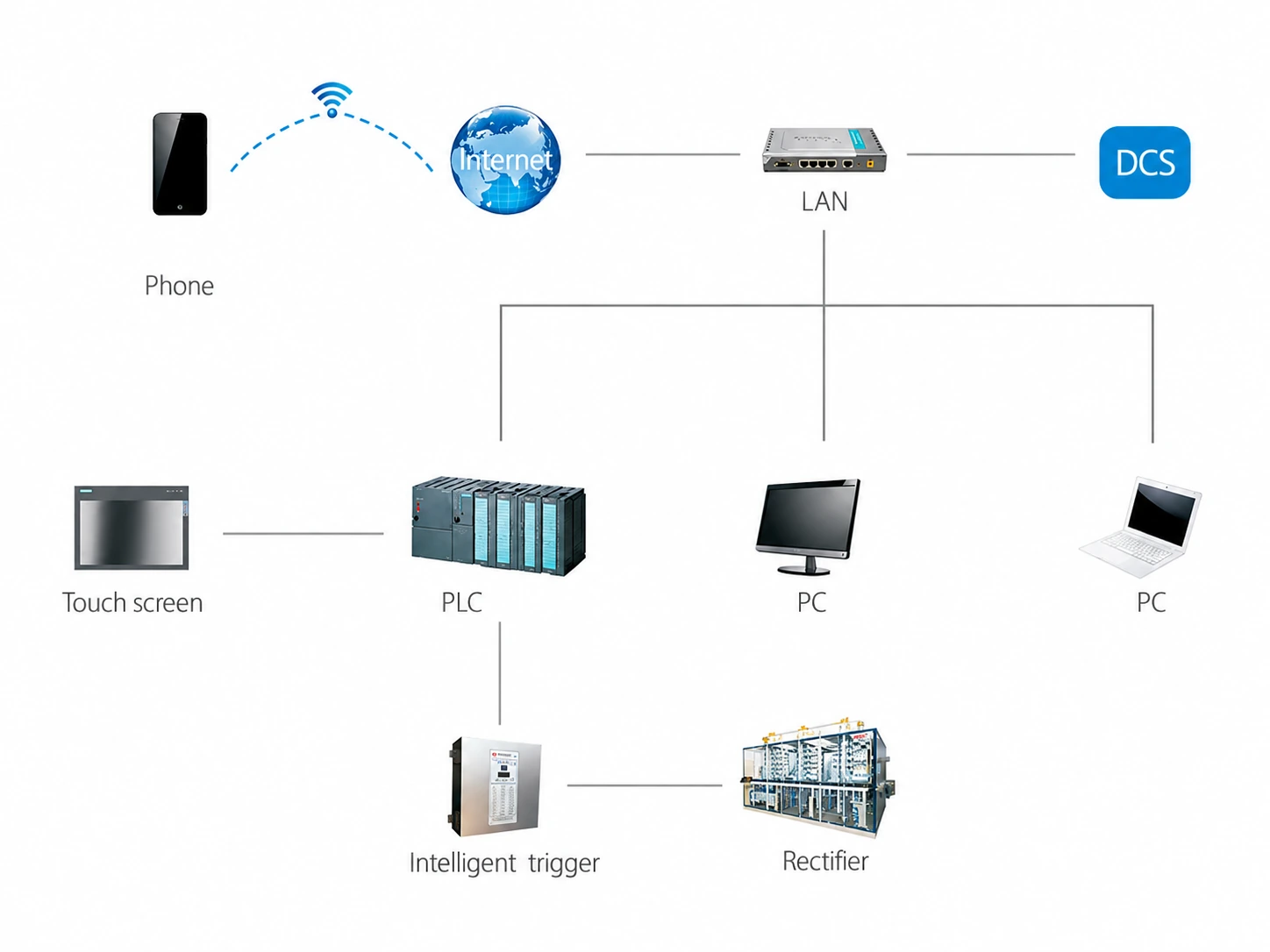
Power-conversion equipment and control equipment work as one system. CPC's intelligent-control diagram connects the rectifier, intelligent trigger, PLC, touch screen, computers and a plant network interface.
The exact controls and signals are defined for each project, but the diagram shows the main layers that need to be coordinated.
Local operation
A touch screen gives operators a local interface, while the PLC coordinates control logic and equipment signals. The points shown on the interface and the permitted operating modes should match the plant's operating practice.
Trigger and rectifier
The intelligent trigger is part of the control path to the rectifier. Its configuration has to match the selected power equipment and the operating requirements of the DC process.
Connection to the plant
CPC's diagram also shows computers and a network connection towards the plant DCS. Defining the communication interface, status points and alarm handling early makes system integration and commissioning more straightforward.
Information to agree during design
- Local and remote operating modes
- Required measurements, status points and alarms
- Plant communication and automation interface
- Control-cabinet location and wiring routes
- Commissioning and operator-training scope